Archivi tag: sdr#

Altra esperienza col volatile!

Non mi sono mai interessato molto al traffico satellitare. Vuoi per mancanza di spazio per le antenne, vuoi perché non si può fare tutto nella vita.
Recentemente mi sono nuovamente fatto incuriosire dalla ISS, per creare delle registrazioni da mostrare agli studenti del corso di “sistemi di telecomunicazione”.
L’idea è quella di mostrare loro gli effetti del rumore e le caratteristiche di un canale satellitare e di cogliere occasione per parlare di LEO, MEO e GEO.

Obbiettivo dell’esperimento: cercare di registrare un segnale audio decente dai passaggi della ISS, utilizzando il ricevitore SDR (Airspy Mini) che ho installato presso il mio ufficio e collegato ad una antenna Diskona della Hoxin (presa su ebay a circa 60 euro). Qualche problemino è emerso:
– ogni tanto la rete di casa faceva perdere qualche pacchetto di troppo;
– il segnale audio della ISS in modalità SSTV è piuttosto bassino;
– sono un cialtrone ad usare MMSSTV;
– ho avuto troppe difficoltà a salvare i dati in “banda base”, perdo frame. Questa cosa è da approfondire!

Malgrado tutti i limiti, anche quelli ambientali (fare acquisizioni con un lattante in braccio non è proprio agevole), qualche cosa nel paniere c’è rimasto. Tre immagini, piuttosto noisy e anche un po’ fuori sincronia. Per essere una “prima volta” best-effort, sono soddisfatto.

Ogni scusa è buona!

Recentemente in casa sono comparsi dei simpatici oggettini che sono detti “baby monitor”. Si tratta di una coppia trasmettitore/ricevitore che dovrebbe dare ai neo-genitori, la sensazione di avere una vita normale, potendo ascoltare da remoto vagiti e gemiti dell’infante.
Non si tratta di una invenzione nuova: ricordo perfettamente che “tanti ani fa” lavoravano in FM a 29700kHz. Si potevano ascoltare molto facilmente con ricevitore, davano parecchio fastidio alle automobiline radiocomandate e li ricevevano anche i walkie-talkie giocattolo (che erano in AM).

I baby-monitor di adesso hanno dimensioni molto contenute, antenne interne e batterie ricaricabili. Per intenderci una cosa di questo tipo. Leggendo le specifiche si apprezza la frequenza di funzionamento compresa tra 1800MHz e 1900MHz, in piena banda DECT. In effetti leggendo il manuale:
– Trasmissione vocale tramite sistema basato su tecnologia digitale DECT.
– Range operativo in campo aperto senza ostacoli di circa 300 metri.
DECT è uno standard che nasce per la telefonia cordless che prevede l’uso di codec audio a 32kbps e 64kbps (G726,G722) su 10 canali nella banda 1800MHz, 1900MHz. Il layer fisico usa FDMA/TDMA con TDD. La modulazione usata è GFSK ma può implementare anche modulazioni più aggressive.

In rete ho trovato un interessante articolo con questo titolo: “RE-DECTED: AN RTL-SDR DECT DECODER”. Nell’articolo si fa riferimento ad un codice contenuto su git-hub: re-DECTED. Il sistema è costruito attorno a Gnuradio e richiede un hardware in grado di sintonizzare i 1900MHz. Per questo è consigliato l’uso di un SDR basato su E4000, il compianto tuner della Elonics o di un ricevitore generico in grado di lavorare a 2.4Ms/s. Anche AIRSPY mini è tagliato fuori: arriva fino a 1700MHz. Pertanto ho deciso di modificare il codice per farlo lavorare con ADALM PLUTO.
Il codice elaborato da “znuh” prevede l’uso di diversi elementi:
– un eseguibile C dectrcv.c che riceve i dati dalla interfaccia localhost, visualizza i frames ricevuti e li redirige alla interfaccia dummy0;
– il codice python che avvia una configurazione su GNURADIO che esegue la ricezione del segnale RF;
– il codice GNURAIO è nel file dectrx.grc che può essere aperto anche con GNURADIO.

Il primo step è modificare il codice grc per introdurre il nuovo “sdr source” adalm pluto. Il primo problema è che il PLUTO non campiona a 2.4Ms/s, ma a 3Ms/s. Il blocco di ricezione invece vuole proprio questo valore. Pertanto è necessario modificare il “rational resampler”. Nella formulazione originale il flusso a 2.4Ms/s viene interpolato per 24 e decimato per 25, ottenendo 2304000. Per avere 2.4Ms/s a partire da 3Ms/s occorre moltiplicare per 0.8, ovvero interpolare per 4 e decimare per 5.

Schema a blocchi originale, credit a znuh
Schema a blocchi modificato per Adalm Pluto

Una volta effettuata la modifica non resta che avviare nella sequenza giusta i software e godersi l’output con “wireshark”. Per creare l’interfaccia dummy in un sistema Ubuntu è meglio seguire questo tutorial.

Output per programma in C, credi znuh
Output del programma GRC, modificato per vedere anche la banda base.
Output di Wireshark, con i pacchetti DECT.

Si potrebbe decodificare anche l’audio ma, sinceramente, non ne ho la minima voglia!
Il nuovo GRC si può scaricare da qui.

WebSdr – PmSDR and RTL-SDR configuration Guide

PMSDR is a small, cheap and high quality SDR Receiver. It was conceived by Martin Pernter Iw3AUT some years ago. I have been using it for both hobby and scientific research, loving its stability and ease of use.

After a long time, during which the receiver collected dust on a shelf in my office, I decided to bring it again to life for the WebSDR project. I’ll not give details on the work of PA3FWM, please visit its site to learn about its work.

The WebSDR project is addressed both to hamradio  enthusiast both to students of the University where I work. SDR technologies are wide spread and it’s time to talk about this subject in the telecommunications oriented courses that are held at University. So I think that the possibility to show some real application of SDR can support the learning path of students, trying to catch their curiosity.

Phase 1 of the projects requires to setup a basic system, using PMSDR and RTL-SDR dongle in order to evaluate performances and get acquainted with WebSDR software.

RTL-SDR.
Configuring the dongle to work in WebSDR is quite easy. It requires the installation of rtl-sdr package in order to provide rtl_tcp command.

After connecting the dongle to the PC, you can check it has been correctly recognised with the lsusb command.

websdr@websdr:~$ lsusb
Bus 002 Device 002: ID 0bda:2832 Realtek Semiconductor Corp. RTL2832U DVB-T

In order to let the dongle receive and forward data, you can use the rtl_tcp program. It will create a socket and stream I/Q samples through it. Put this command in your rc.local file to execute it as a daemon during computer boot.

rtl_tcp -a 127.0.0.1 -p 65144 -f 145000000 -d 0

Remembre that if you want to change the receiving frequency, you have to modify THIS script, otherwise nothing will happen. The command stated shows -p switch, in order to set the streaming port, the -f to set the working frequency and -d to address a specific device in case you have multiple dongles.

WebSDR configuration lines for RTL-SDR are very simple:
#rtl_sdr per i 3cm
band 3cm
device !rtlsdr 127.0.0.1:65144 85
samplerate 2048000
centerfreq 681000
antenna lnb

The “85” shows the amount of ppm correction to apply in the frequency.

PMSDR
Setting up the PMSDR may be a little “tricky”. First of all you have to consider this is a “near-zero IF SDR”: it will provide an audio baseband signal to a sound-card. First of all you have to setup an ALSA sound system. If you (like me) are not very familiar with Linux audio world, well “don’t panic”. The sound-card I use with PMSDR is USB connected. So let’s check it:

websdr@websdr:~$ lsusb
Bus 002 Device 002: ID 0bda:2832 Realtek Semiconductor Corp. RTL2832U DVB-T
Bus 002 Device 001: ID 1d6b:0002 Linux Foundation 2.0 root hub
Bus 008 Device 002: ID 041e:30df Creative Technology, Ltd

Now it’s time to hadle permissions for using the soundcard:
websdr@websdr:~$ cat /etc/udev/
hwdb.d/ rules.d/ udev.conf
websdr@websdr:~$ cat /etc/udev/rules.d/90-creative.rules
ACTION==”add”, SUBSYSTEM==”usb”, SYSFS{idVendor}==”041e”, SYSFS{idProduct}==”30df”, GROUP=”audio”
websdr@websdr:~$

Now you should be able to use the “magic” command:
websdr@websdr:~$ arecord -l
**** List of CAPTURE Hardware Devices ****
(…)
card 1: Pro [SB X-Fi Surround 5.1 Pro], device 0: USB Audio [USB Audio]
Subdevices: 0/1
Subdevice #0: subdevice #0

Before trying to go any further is mandatory to check if ALSA can support your hardware. In any other case all your efforts will result in a total loss of time. According to ALSA site, the SB X-Fi in UNSUPPORTED.

So let’s give up and try another Audio Adapter, this time embedded device:

root@websdr:~# arecord -l
**** List of CAPTURE Hardware Devices ****
card 0: Intel [HDA Intel], device 0: ALC662 rev1 Analog [ALC662 rev1 Analog]
Subdevices: 1/1
Subdevice #0: subdevice #0
card 0: Intel [HDA Intel], device 2: ALC662 rev1 Alt Analog [ALC662 rev1 Alt Analog]
Subdevices: 1/1
Subdevice #0: subdevice #0

WebSDR configuration file wants to know 3 parameters: card,device, subdevice. Using this command we can retrive all data we need, as the card number is “0”, the device is “0” and the device is “0” as well. Write this parameters and  forget them.

Now you need a way to interact with PMSDR internal PIC in order to program the internal oscillators. More over, if your PMSDR is equipped with a Downconverter board, you have to program it as well. There is a small,yet realiable and easy-to-use, client which was written by Andrea Montefusco and is available on sourceforge. You have to build it, so install gcc and read carefully the installation notes. After the program has been built, run it by “pmsdr”. There is an embedded help system.

Linux PMSDR 2.0/2.1 control program, version 2.5.1
Original code by Martin Pernter IW3AUT
Linux porting by Andrea Montefusco IW0HDV
www.obdev.at – DG8SAQ-I2C
Interface 0 claimed.
Firmware reports version 2.5.0
Si570 detected.
CY22393 detected.
Downconverter Board detected.
Si570 on Downconverter Board detected.
Type ‘help’ or ‘?’ for get online help.
/tmp/PMSDRcommands FIFO unavailable [No such file or directory]
Input switched to standard input.
—> help

<command> [<value>] //
FREQUENCY : f <d> // f 7050000 == ( 7.050,000 kHz)
F3Harmonic : f3 <d> // f3 100300000 == ( 100.300 MHz)
FREQUENCY Dc : fd <d> // down converter conversion frequency in Hz
FILTER : filter <d> // 0 (no filter),1 (2-6MHz),2 (5-12MHz),3 (10-24MHz), 4 (<2MHz)
DFILTER : dfilter <d> // 0 (down converter bypass), 1 (VHF filter), 2 (UHF filter), 3 (unfiltered)
QSDbias : qsdbias <d> // qsdbias 512 (default), 346-692 (interval allowed)
QSDmute : qsdmute <on,off> // qsdmute on, qsd off (i.e. 0,1
STOREfreq : memf <d> // store init freq into PMSDR EEPROM f 585000 == (585,000 kHz)
STOREfreq3 : memf3 <d> // store init f3/3 into PMSDR EEPROM
RESTORE freq : rmemf // restore init freq from PMSDR EEPROM
PRINTlcd : plcd <col> <row> <message_text> // print the message text at specified coord on the LCD
QUIT : quit // exit from pmsdr
HELP : help // this help!

INPUT-SEQUENCE-example:
->help,filter 4,f 1611000,f 585000,memf 585000,filter 0,f3 100300000,quit

In order to set PMSDR for 2m reception you need to program downconverter first:
dfilter 1
fd 116000000
In this way 144MHz is downconverted to 28MHz. So the next step is
filter 0
f 28000000
save it!
memf 28000000.

Now let’s go back to WebSDR and let’s write some configuration for PMSDR as well:
#pmsdr per i 2m
band 2m
#alsa devices are: card/dev/subdev
device $hw:0,0,0
samplerate 96000
centerfreq 144320

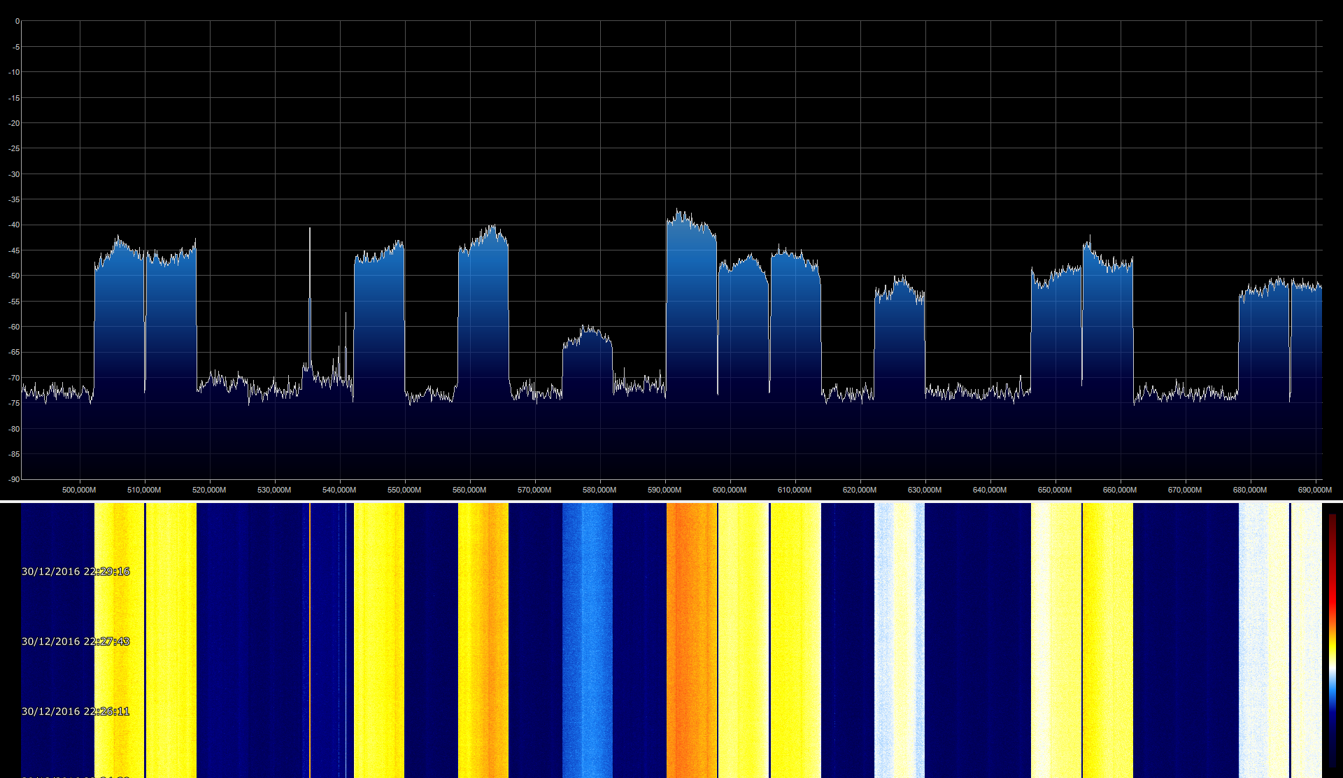
Some screenshot taken with lab equipment, showing the receiver busy in demodulating a carrier at 144.290 MHz (frequency choosen where the waterfall was clean).

So the work is over. Everything should be fine and you should be able to run the server. I’m still very disappointed that I was unable to use a better soundcard. I did some testing with a PCI M-Audio Audiophile 2496 but I was unable to let it work.

AirSpy

Finalmente è arrivata!!!
(questo articolo è in attesa di essere pubblicato dal 3 ottobre 2016)

Packaging minimale, ottima imbottitura, grande protezione  e dentro la chiavetta! Completamente in alluminio, con un bel connettore SMA femmina installato. Il tempo di collegarla al PC e già funziona. Non richiede driver o procedure perverse di installazione. Davvero un dispositivo Plug ‘n Play.

img_20161003_122946

Ho scaricato l’ultima versione di SDR# ed ho avviato la ricezione: eccellente! Il front-end è meno predisposto alla intermodulazione, lo spettro visualizzato è pulito ed i segnali si vedono decisamente peggio.

Forse lascia sul terreno qualche cosa in termini di guadagno: le conversazioni su satelliti MIL a 256 MHz non riesco a riceverle, ma sono piccoli dettagli.

La possibilità di visualizzare una porzione molto ampia di spettro è fantastica ed apre la scena a numerose applicazioni, anche in ambito didattico. Ecco qualche screenshot di SDR# della simpatica applicazione “analizzatore di spettro” che vedo molto bene in congiunzione con il generatore di rumore ad ampio spettro per fare qualche prova sui filtri in cavità. Antenna televisiva, in paese. La prima con 100MHz di span e la seconda in full Bandwidth.

Costa… vero… ma ne vale davvero la pena!!!

SDR# sempre più forte.

Questa mattina ero alla ricerca di un modo per potere ricevere più canali contemporaneamente con SDR#. Mi sono imbattuto in questo sito che presenta solo plug-in per il software SDR#.

Il sito è in Russo, ma google translate consente una facile lettura in Inglese. Dopo qualche lettura mi sono deciso ad utilizzare l’installer proposto dal sito ed a inserire tutti  i plugin nella mia versione di SDR#. L’installer ha fatto bene il suo dovere ed ha richiesto solo un intervento manuale per configurare i VFO multipli, andando ad editare il file “Plugins.xml”.

<sharpPlugins>
    <add key="IQ Balancer" value="SDRSharp.IQCorrection.IQCorrectionPlugin,SDRSharp.IQCorrection" />
    <add key="Noise Blanker" value="SDRSharp.NoiseBlanker.NoiseBlankerPlugin,SDRSharp.NoiseBlanker" />    
    <add key="BasebandRecorder" value="SDRSharp.BasebandRecorder.BasebandRecorderPlugin,SDRSharp.BasebandRecorder" />
    <add key="TimeShift" value="SDRSharp.TimeShift.TimeShiftPlugin,SDRSharp.TimeShift" />
    <add key="DSD" value="SDRSharp.DSD.DSDPlugin,SDRSharp.DSD" />
    <add key="DCSDecoder" value="SDRSharp.DCSDecoder.DCSDecoderPlugin,SDRSharp.DCSDecoder" />
    <add key="CTCSSDecoder" value="SDRSharp.CTCSSDecoder.CTCSSDecoderPlugin,SDRSharp.CTCSSDecoder" />
    <add key="Digital Audio Processor" value="SDRSharp.DAP.DAPPlugin,SDRSharp.DAP" />
    <add key="Digital Noise Reduction" value="SDRSharp.DNR.DNRPlugin,SDRSharp.DNR" />
    <add key="Zoom FFT" value="SDRSharp.ZoomFFT.ZoomFFTPlugin,SDRSharp.ZoomFFT" />    
    <add key="AudioRecorder" value="SDRSharp.AudioRecorder.AudioRecorderPlugin,SDRSharp.AudioRecorder" />    
    <add key="Frequency Scanner" value="SDRSharp.FrequencyScanner.FrequencyScannerPlugin,SDRSharp.FrequencyScanner" />
    <add key="Frequency Manager" value="SDRSharp.FreqMan.FreqManPlugin,SDRSharp.FreqMan" />
    <add key="AuxVFO-1" value="SDRSharp.AuxVFO.AuxVFOPlugin,SDRSharp.AuxVFO" />
    <add key="AuxVFO-2" value="SDRSharp.AuxVFO.AuxVFOPlugin,SDRSharp.AuxVFO" />    
    <add key="AuxVFO-3" value="SDRSharp.AuxVFO.AuxVFOPlugin,SDRSharp.AuxVFO" />
    <add key="AuxVFO-4" value="SDRSharp.AuxVFO.AuxVFOPlugin,SDRSharp.AuxVFO" />
</sharpPlugins>

E’ un mare di roba. Lo so. Le ultime 4 righe consentono di avere 4 VFO indipendenti e di ascoltare quini 4 canali contemporaneamente ed in modo del tutto indipentente. Il front end adesso è piuttosto affollato:

Sdr_Complete

Un dettaglio sulla barra di sinistra:

Sdr_Complete1

Il breve video che segue mostra l’uso di 4 VFO per monitorare 5 canali contemporaneamente (4 VFO + VFO di sintonia). Interessante notare come, una volta agganciata la frequenza, il VFO la tracci anche al variare della frequenza centrale di sintonia.

Buon Ascolto!